
In both CATIA V5 and 3DEXPERIENCE, Publications act as “ports” for establishing connections (such as assembly constraints, external references, etc.) between parts and/or products.
Instead of directly pointing to the geometrical elements within the models, the connections now point to the “ports” (i.e., publications) that, in turn, point to the actual geometrical elements in the models. And the owner of the model is responsible for ensuring that the publication points to the correct geometrical element in the model.
The benefits:
· Stable and geometry-independent connections and links between the models.
· Avoiding unauthorized links between the models, in a collaborative design environment.
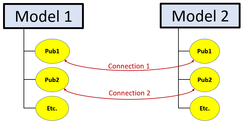
Figure 1
Consider the diagram below, which describes what happens when one model (the “child”) references a publication in another model (the “parent”). The diagram highlights that, in fact, we’re dealing with two kinds of links here:
· Link #1: Links the Publication to the actual geometry in the model. In CATIA V5, this link is implicit, i.e., invisible to the user. In 3DEXPERIENCE, this link is explicit, and might need to be synchronized if the model changes.
· Link #2: Links the geometry in the “child” model with the Publication in the “parent” model. In both CATIA V5 and 3DEXPERIENCE, this link is explicit, i.e., visible to the user.

Figure 2
This is where the similarity between V5 and 3DEXPERIENCE ends because the implementations are quite different.
In this article, I will describe how to work with Publications in CATIA 3DEXPERIENCE.
To create a new Publication, first activate the 3D Part level for the model in which you want to create the Publication. This should activate the Assembly Design app.

Figure 3
Click  (Create a Publication) and select the geometrical element you want to publish. In the Publication dialog box, enter in the Functional Name and click OK to complete.

Figure 4
The new Publication displays in the tree.
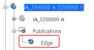
Figure 5
Now – what happens if you modify the geometry of the part? The Publication displays the symbol shown below, telling you that it needs to be synchronized.
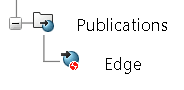
Figure 6
To manually synchronize the Publication, select  (Links and Relations) to open the Edit Links and Relations dialog box. Note that the Status shows “red thumbs-down” symbol. Click
  to synchronize.

Figure 7
The Publication gets synchronized, and the Status symbol changes to “green thumbs-up”.

Figure 8
Since manual synchronization could be a pain, there is a setting that enables automatic synchronization. Go to Preferences > App Preferences > 3D Modeling > Systems Architecture > Publication and enable Automatic update of product level publications.

Figure 9
Next topic – referencing a Publication from another model.
First, if you want to avoid unauthorized links between the models, go to Preferences > Common Preferences > Object Properties > 3D Shape > Infrastructure and activate Restrict external selection with link to published elements. This way, if a designer tries to reference a non-published geometry from another model, the system won’t allow that.

Figure 10
Once you reference a Publication from another model, it creates a link that is placed into the External Reference container, and it displays the “green thumbs-up” symbol.

Figure 11
Now, what happens if you modify the referenced geometry in the “parent” model? The link in the “child” part displays the “red thumbs-down” symbol, which means the link is out of sync.

Figure 12
To manually synchronize the link, select (Links and Relations) and click .
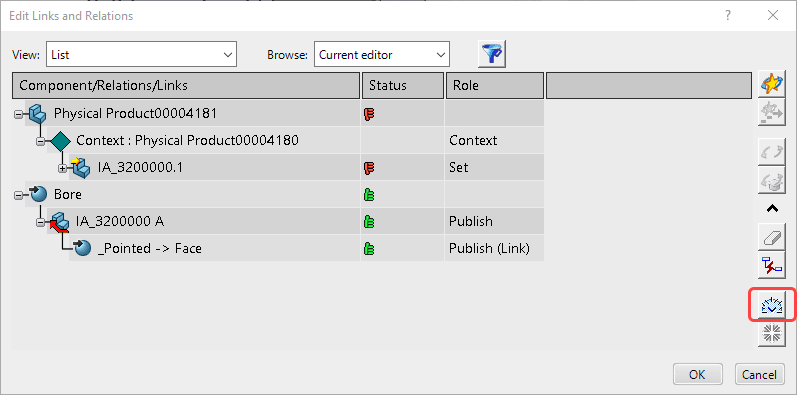
Figure 13
The “red thumbs-down” symbols change to “green thumbs-up”.

Figure 14
The “child” part might still require an update – click  to do so.
To make things a little easier, you can request automatic link synchronization when updating a part. To do so, go to Preferences > Common Preferences > Object Properties > Infrastructure and activate Synchronize all external references when updating the 3D shape option.

Figure 15
That seems to be about it. If you have any further questions or would like to explore more 3DEXPERIENCE features, feel free to contact us at training@rand.com.
About the Author
Visit Website More Content by Iouri Apanovitch


